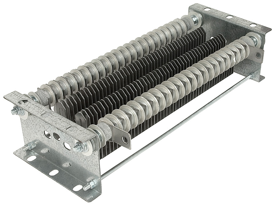
Resistor Elements
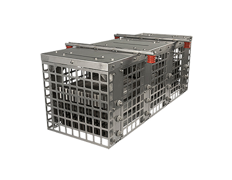
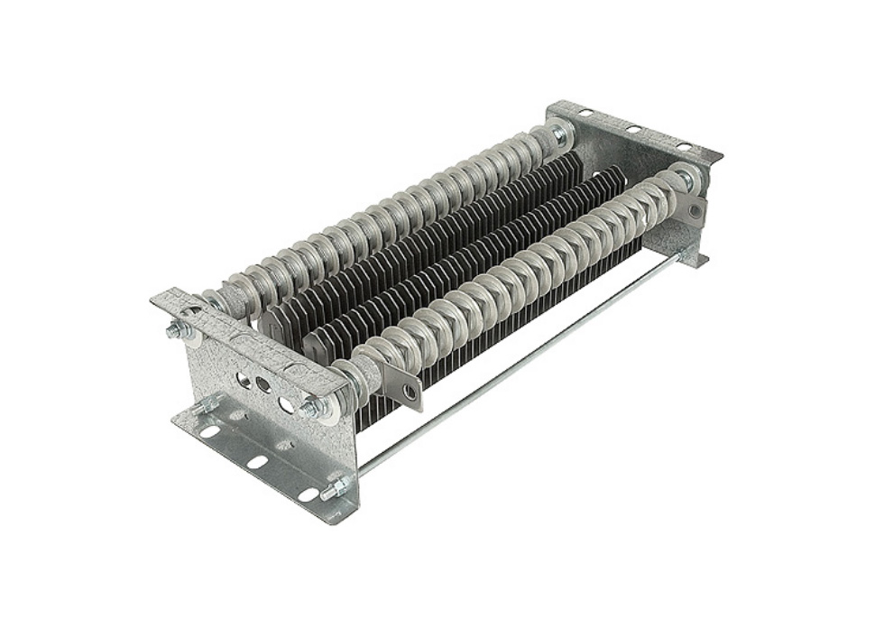

Being first a manufacturer of industrial power resistors, Post Glover has a vast array of Dynamic Braking Resistors to choose from. This allows us to offer the best possible technical and economic solution for your particular brake resistor application. We have worked with many OEMs and built a broad knowledge of their product specifications for dynamic brake resistors, so when you call in requesting a part, Post Glover can cross-reference the part number and quote the needed part.
Post Glover is an original Rockwell Automation Partner for Dynamic Braking Resistors and has pre-engineered designs for RA VFD’s to expedite the selection, ordering and manufa cturing processes. You can rely on the industry’s most innovative resistor manufacturer with over 100 years of industry experience. Click here to access Rockwell’s Product Configurator for PGR Dyanmic Braking Resistors. Download the PowerFlex Catalog with specifying information here: PGR PowerFlex DBR Catalog.
How Dynamic Braking Resistors Work
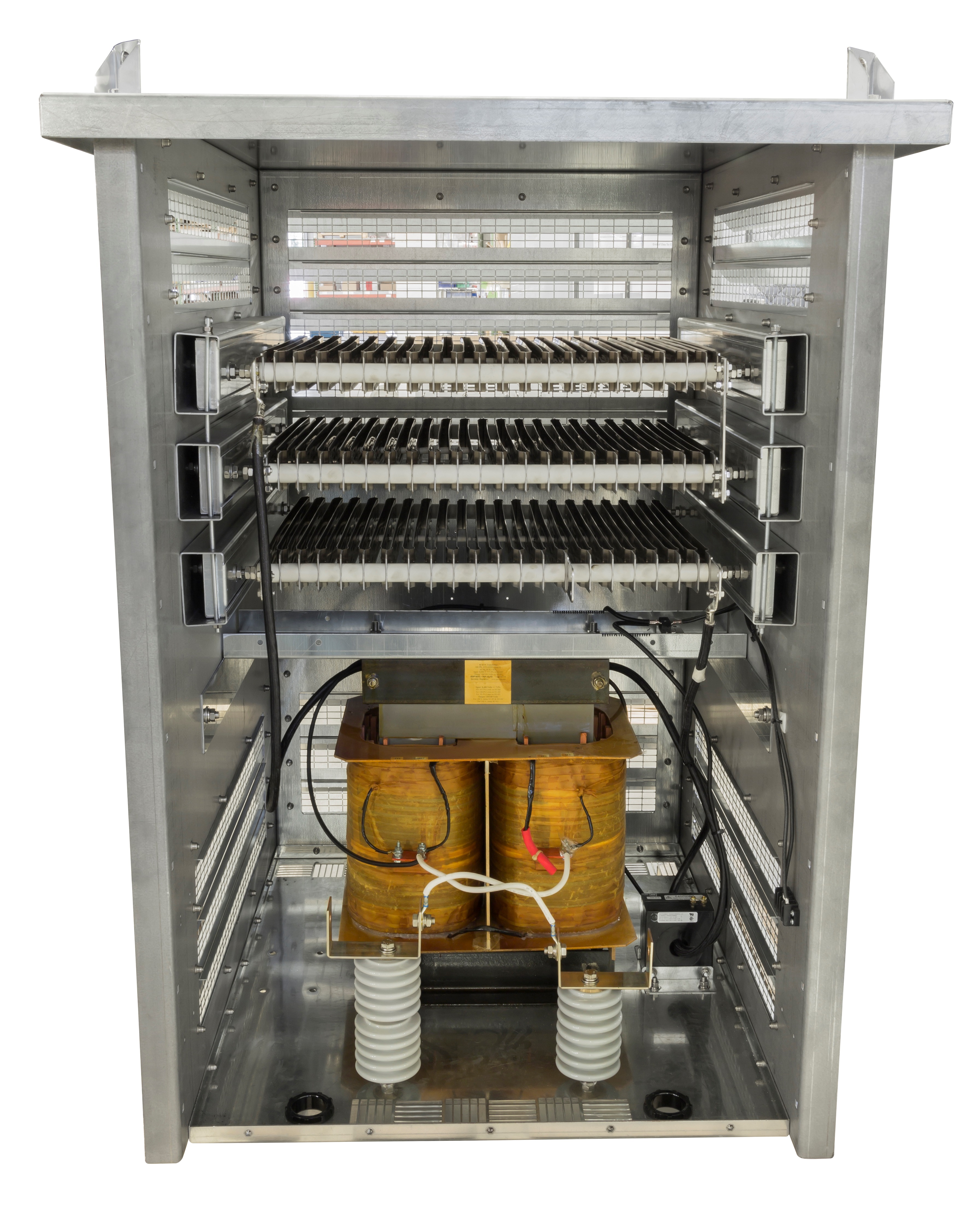
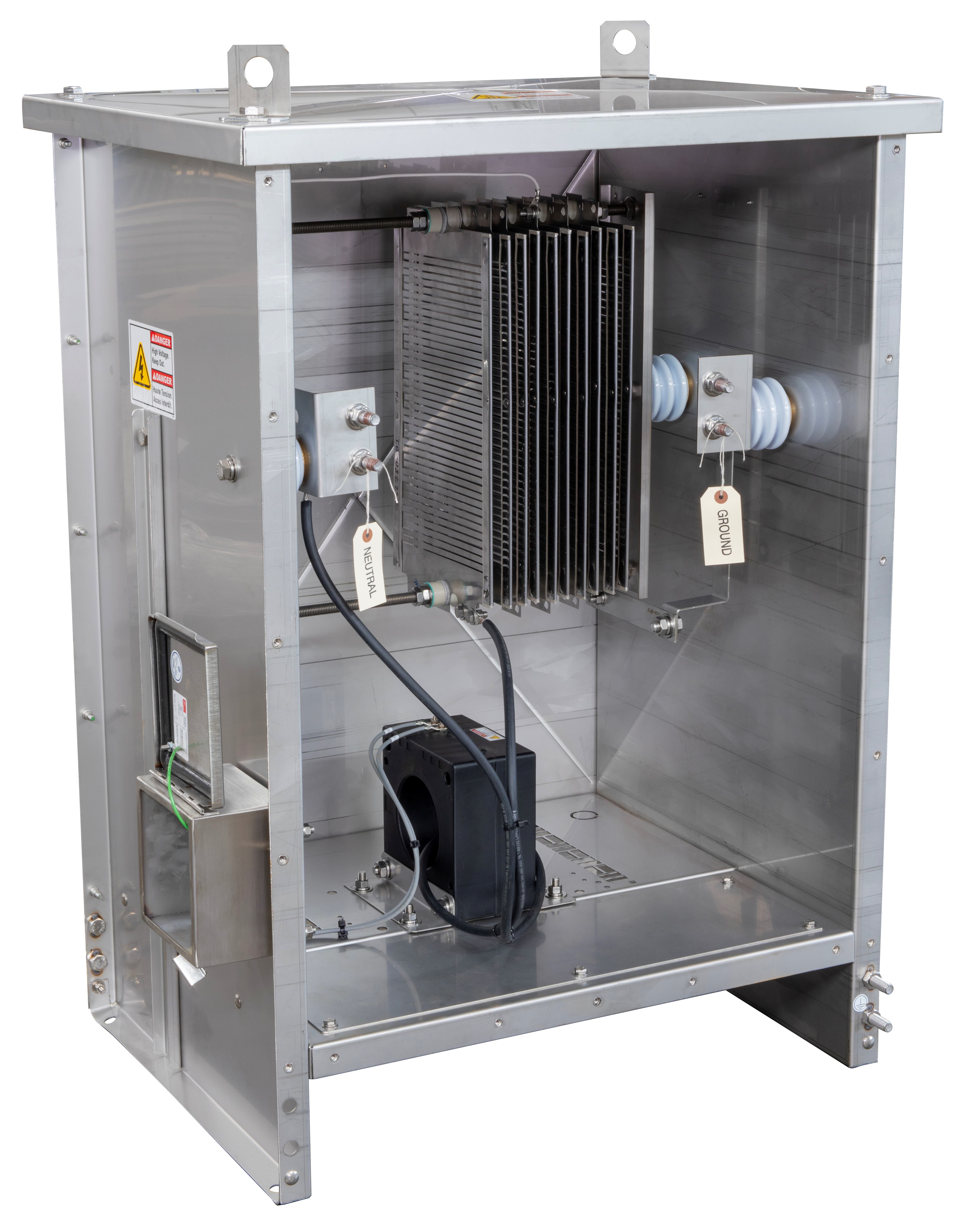
State of the art AC Variable Frequency Drives (VFD) are commonplace today, creating the need for reliable, proven Dynamic Braking Resistors that can be delivered quickly, completely assembled, and ready for convenient installation at the job-site. Dynamic Braking Resistors are used with AC VFD’s to produce a braking torque in the motor during overhauling conditions. The dynamic braking resistor is connected across the DC bus and will see voltages as high as 800 volts.
The drive manufacturer normally determines the power rating (watts) needed to prevent overheating during braking duty. The peak braking current is determined by the specified resistance value. Each drive manufacturer specifies a resistance range with a minimum to prevent overcurrent and damage to the drive and a maximum value to give adequate lower dissipation capability.
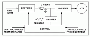
A three-phase variable frequency drive (VFD) consists of three basic components – rectifier, DC line, and inverter – and a control system to manage these three components as illustrated. The rectifier converts the three-phase 60Hz AC input to a DC signal.
Depending on the system, an inductor, a capacitor, or combination of these components smooths the DC signal (reduces voltage ripple) in the DC link part of the VFD. The inverter circuit converts the DC signal into a variable frequency AC voltage to control the speed of the induction motor.
During braking, the VFD ramps the frequency to zero. The rotational energy of the motor and load are driven back through the inverter to the DC bus.


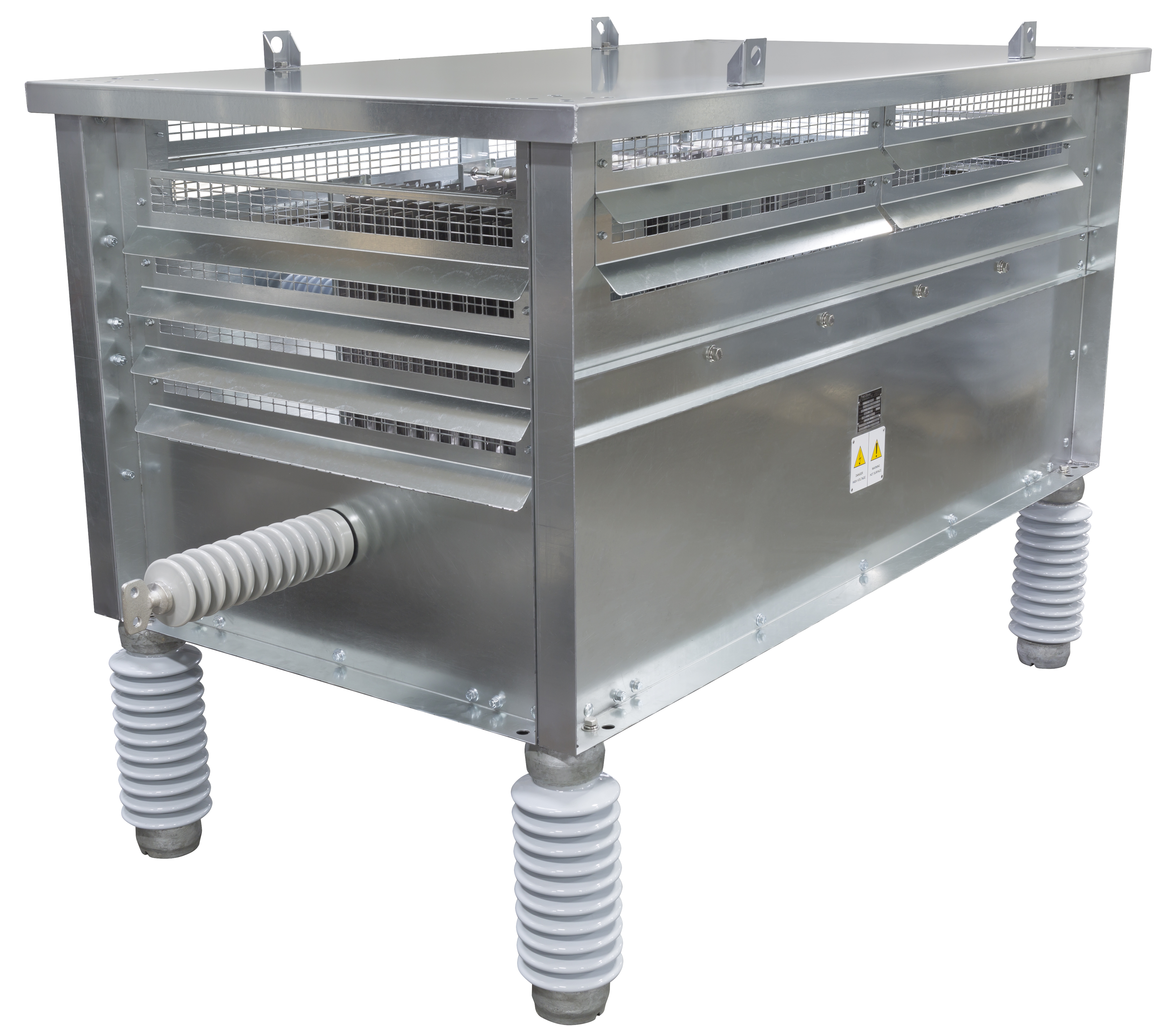
Standard features and options for all Post Glover Dynamic Braking Resistors
- Standard Nema 1 Enclosure Design
- Thermal overloads
- Two Point terminal block
- Factory Tested
- Convenient Conduit Knockouts
- Options: Powder Coated, Nema 3R, Stainless Steel