

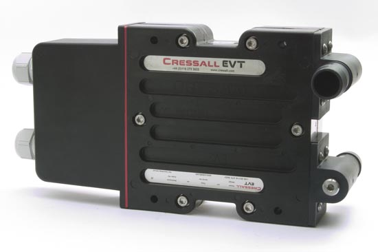
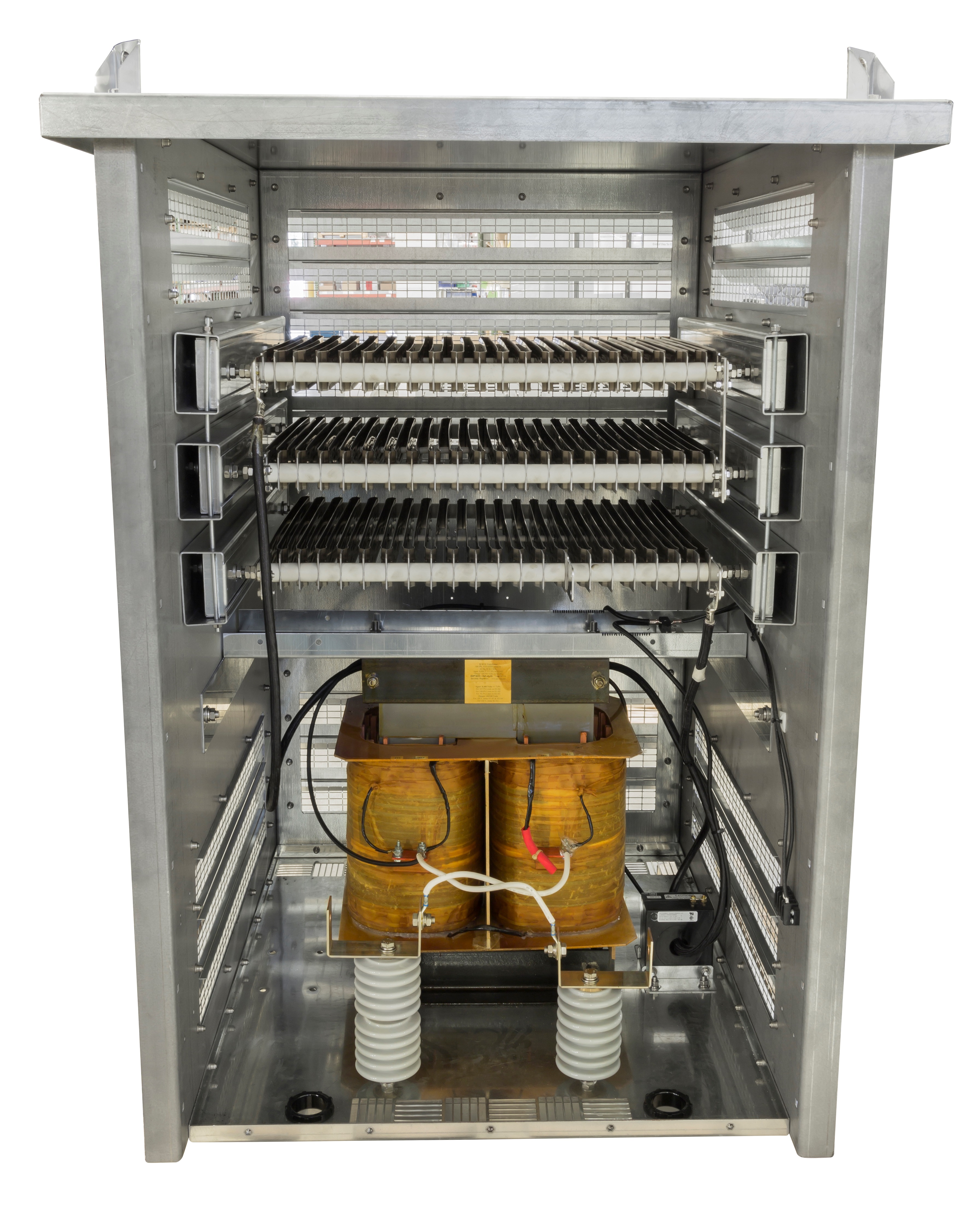
Resistor Elements


High Resistance Grounding Specifications
1.0 SCOPE
This specification details the minimum technical requirements of high resistance neutral grounding equipment.
2.0 CONFORMANCE TO NATIONAL STANDARDS
The equipment shall be constructed, wired and tested to the following standards:
- Underwriters Laboratories Inc. (UL)
- Standard NMTR, NMTRT
- Institute of Electrical and Electronics Engineers (IEEE)
- Standard 32-1972: Requirements, Terminology, and Test Procedure for Neutral.
- Standard 142-1991: Grounding of Industrial and Commercial Power Systems.
- International Electrical Commission (IEC)
- Standard 529 & 144: Protection Degree for Enclosures
- International Organization for Standardization (ISO)
- Standard 9001:2000: Quality Management Standards and Guidelines
3.0 NEUTRAL GROUNDING RESISTOR
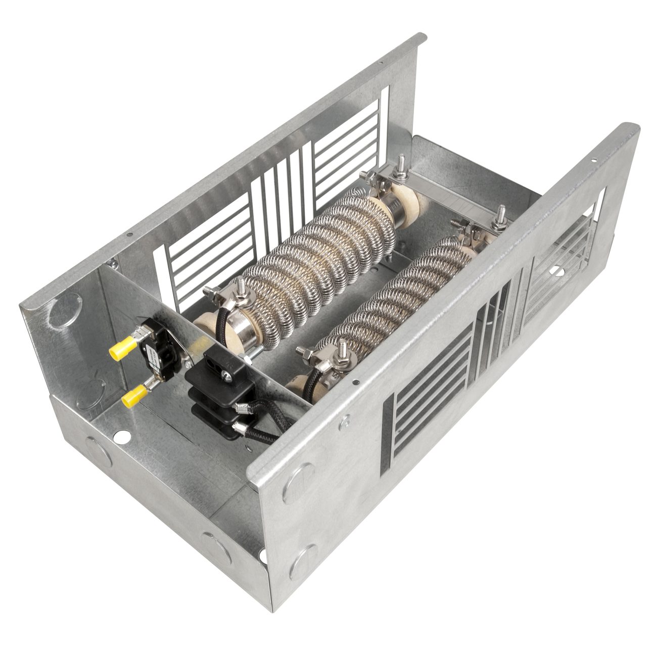
3.1 The neutral grounding resistor will consist of high grade chromium stainless steel or nichrome elements and terminals of high corrosion resistance, double insulated, durable for long years of service, and having extremely high & stable electrical resistivity.
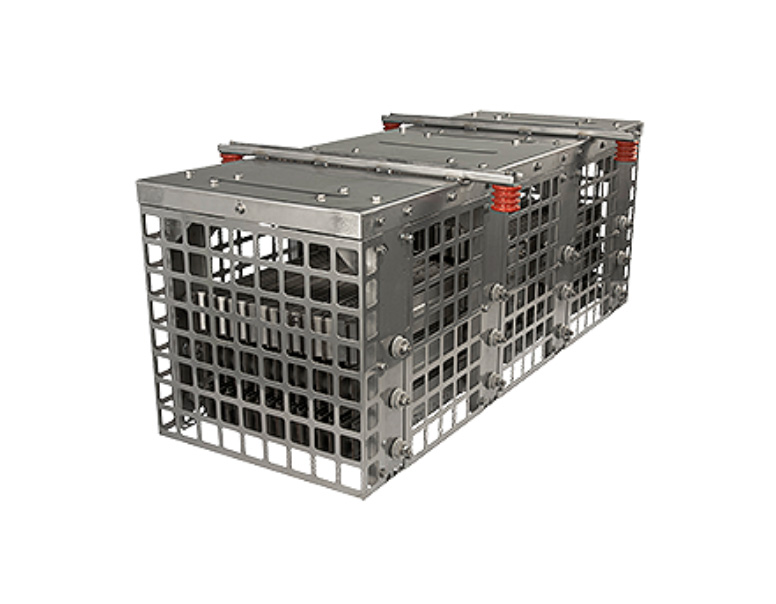
3.2 If more than one frame is required, series connections will be solid copper bus on grid style resistors, teflon wire on wirewound style resistors.
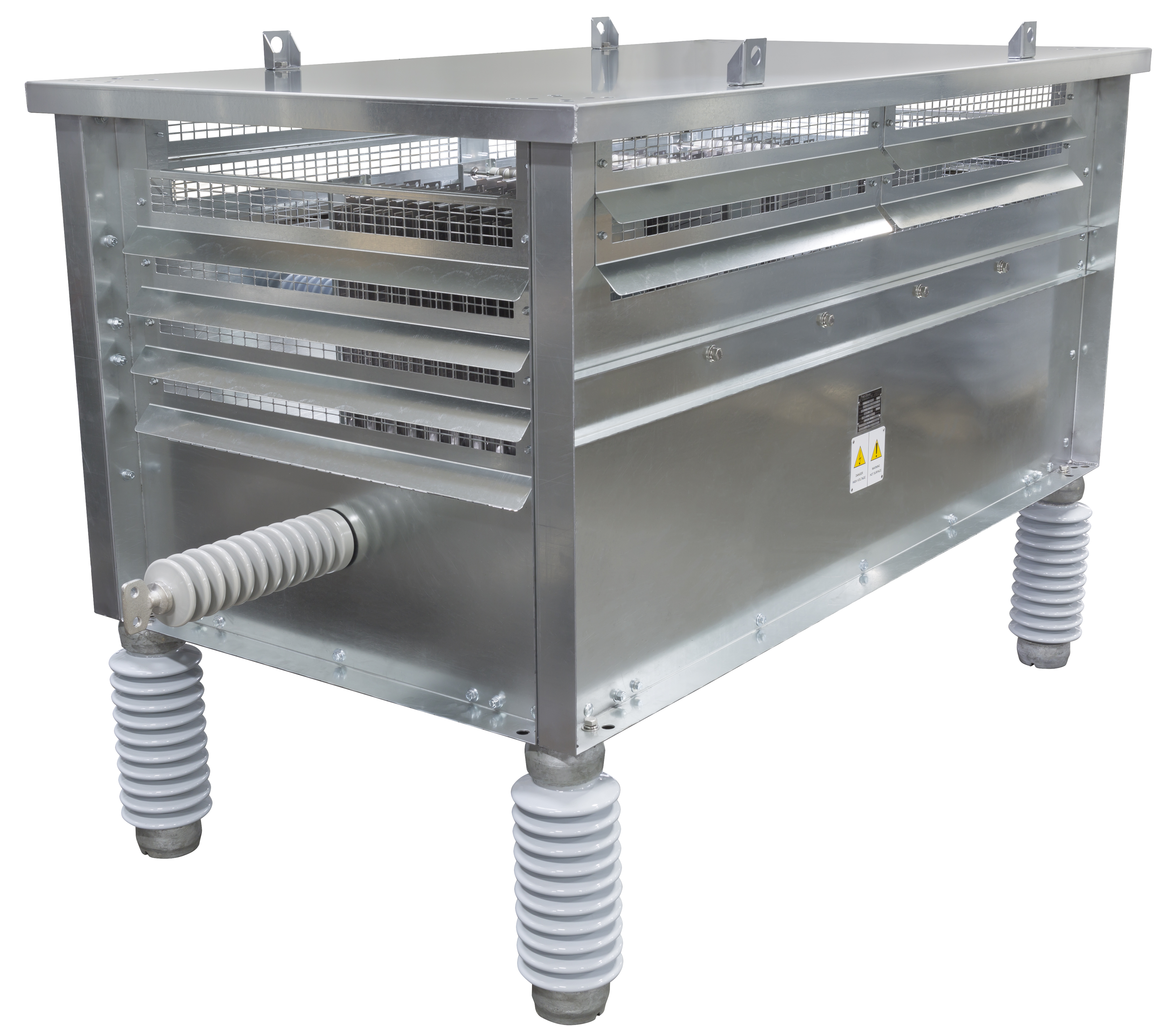
3.3 The resistor frame(s) will be mounted on standoff insulators with a rating equal to or greater than the line-to-neutral voltage.
3.4 The standard temperature rise will be 385°C.
3.5 The resistors shall be tapped at 2, 3, 4, 5, 6, 8 and 10 amps. The taps will be wired using teflon insulated wire to a terminal block situated for safe access by the user to simplify coordinating the high resistance grounding system to a particular network?s charging current.
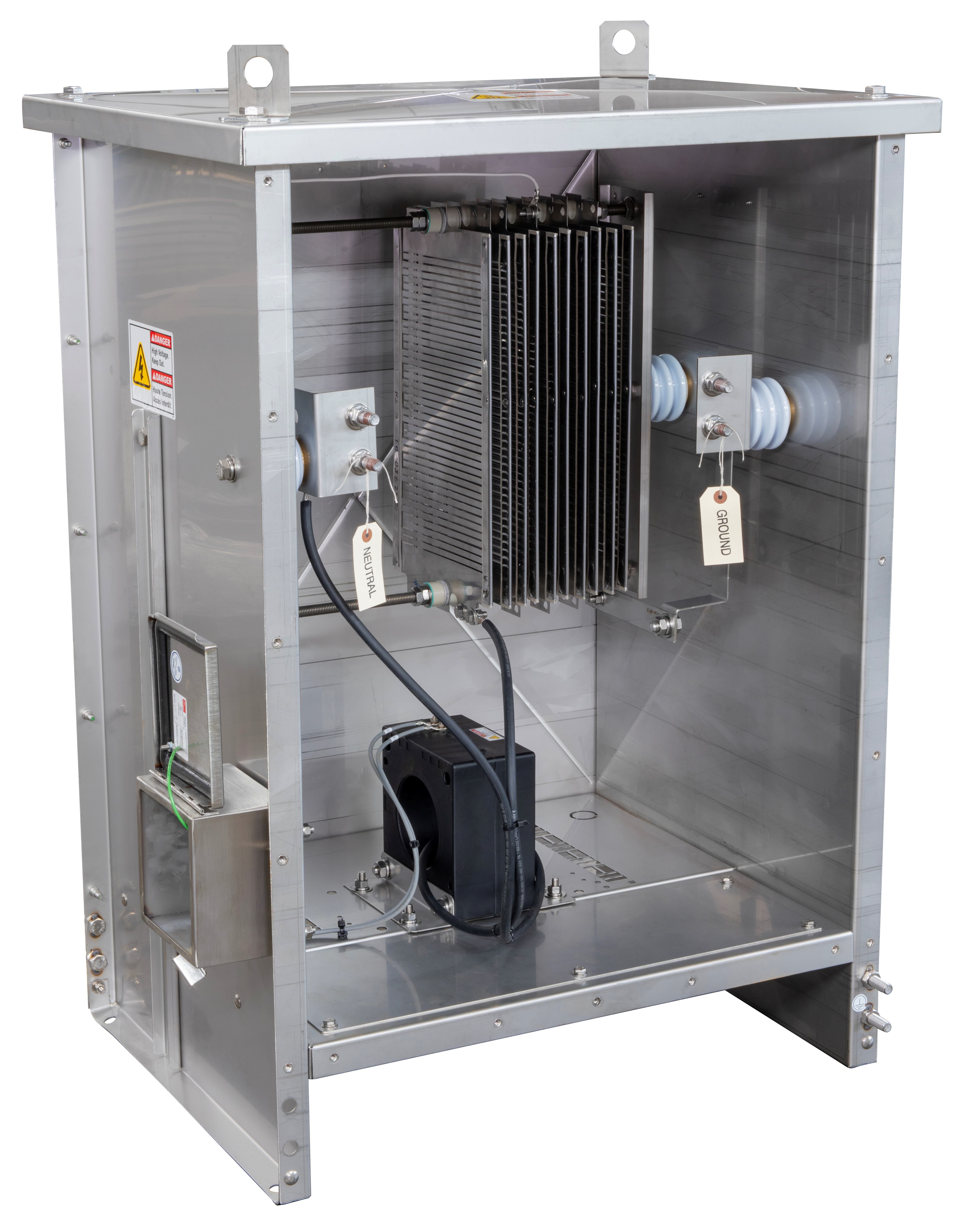
4.0 ENCLOSURE
4.1 The assembly shall be a NEMA 3R free-standing enclosure housing both the control and resistor components. The enclosure shall be suitable for indoor use also. The enclosure shall be ANSI-61 gray powder-coated, galvanneal steel.
4.2 The resistor assembly shall be housed in a compartmentalized section of the enclosure to shield the controls from excessive heat. Ventilation shall be sufficient to properly cool the resistors in the event of a fault and maintain a safe environment for the controls.
4.3 The enclosure shall include an anti-condensation heater with adjustable thermostat suitable for use at rated system voltage.
4.4 The enclosure will provide fused terminations for all three phases. These inputs will be used to identify which phase is grounded in the event of a fault and feed the included control power transformer.
4.5 The enclosure shall have a dedicated ground bus in the bottom of the unit for connection to the user?s ground grid.
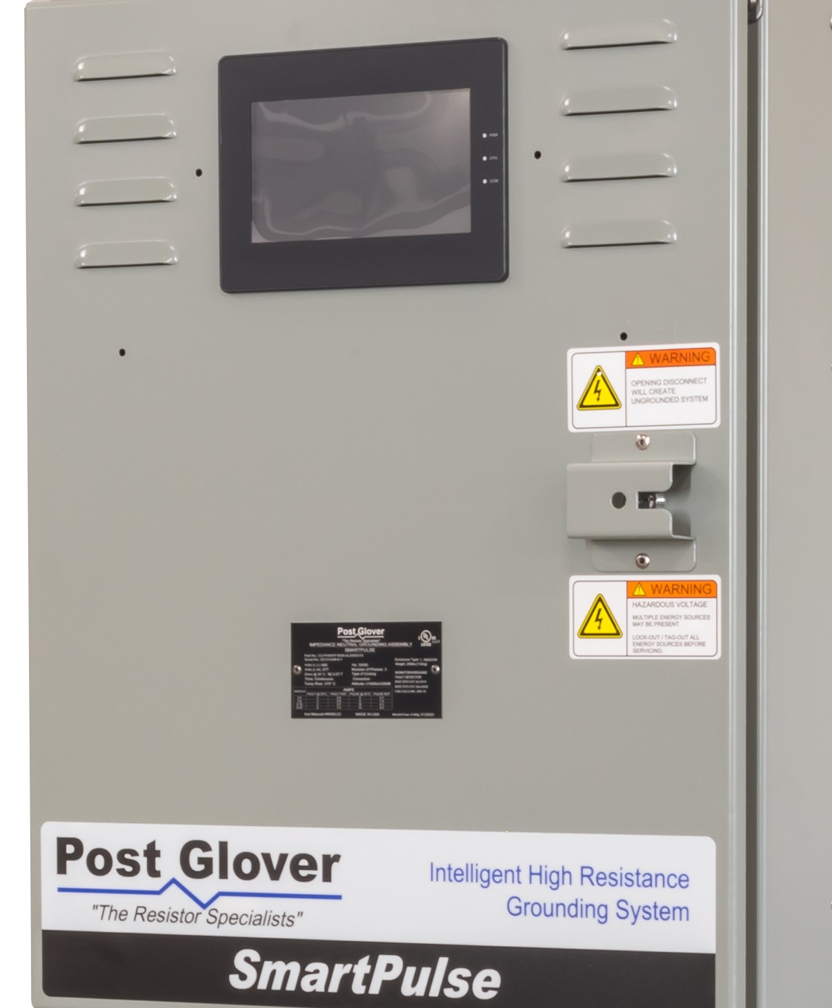
5.0 CONTROLS
5.1 All control circuitry will operate on 120 Volts AC supplied via control power transformer. Controls shall be protected against electrical surges.
5.2 All control wiring will be rated at 600 Volts a.c. Wiring must be sufficiently supported within the enclosure.
5.3 The high resistance neutral grounding equipment will contain the following equipment on the front of the unit as standard:
a. Fusible Disconnect Switch. The five pole disconnect switch (three phases, neutral to grounding resistor and neutral to sensing resistor) will be equipped with properly sized fuses (class CC).
b. Indicating Lamps. Three LED pilot lights indicating Normal status, Ground Fault in system and Pulsing in operation.
c. Horn to annunciate alarm conditions.
5.4 A digital interface unit with display screen containing the following functions:
a. Alarm View, Acknowledge and Clear Push-buttons
b. System Test Push-button. The Test push-button shall be inoperable during a ground fault to prevent an accidental phase to phase fault. The push-button shall simulate a ground fault to measure proper operation of the HRG system.
c. System Reset Push-button
d. Lamp test feature to verify three lights listed above are functional
e. Pulse on/off push-button. The pulsing duration can be set by the user in the software.
f. Menu, Edit, Escape and Enter buttons to navigate the operating software and interface screens to program system parameters and alarm settings.
g. Software to Data Log / Trend system conditions. The unit should have an event log and an alarm log with date and time recording. The alarm log should record any ground fault events as well as the voltage and current readings. The event log should record any testing, pulsing activation, etc. A minimum of 200 records in either log is required.
h. Ethernet port for Communications. This allows system parameters and conditions to be remotely accessed and viewed.
5.5 The unit shall monitor and annunciate the following conditions:
a. Under or over-current through the neutral
b. Under or over-voltage on the neutral
c. Specific phase faulted
d. Failure in resistor path. The equipment shall include a Sensing Resistor Circuit to detect and annunciate breakdowns in the neutral through resistor to ground path.
5.6 The function to monitor neutral voltage and current will incorporate an adjustable time delay function to avoid spurious alarms. Additionally, the function will be tuned to detect only the fundamental frequency component to avoid false alarms.
5.7 The equipment shall include a pulsing feature to assist in locating faults. The pulsing cycle shall be adjustable by the user.
5.8 The unit shall be capable of measuring the system charging current by shorting one phase directly to ground. This shall be interlocked with the fault detection system to prevent measurement during a ground fault.
5.9 The optional portable ground detector will be a ?split core? type ammeter with a multiple range switch. The clamp must be capable of enveloping a minimum 6? diameter. A short circuiting switch should be provided, along with a carrying case. The handle must be insulated for use on 4,160 volt system.
6.0 MARKINGS
6.1 Wiring is to be numbered consistent with the wiring diagrams. Wire numbers are to be on adhesive labels at each end of the wire.
6.2 Internal control panel components are to be identified with durable adhesive labels. Text may utilize an abbreviated legend, as long as that legend is identified on the wiring diagram.
6.3 Components on the front control panel are to be permanently identified.
6.4 A list of operating instructions is to appear on the front face of the control panel. These instructions are to cover normal, test, and fault conditions.
6.5 Each assembly must include a permanently attached nameplate specifying the following information:
- Manufacturer
- Volts Line-to-Neutral
- Amps
- Ohms
- Seconds
- Extended Time (if applicable)
- Part Number or Drawing Number
7.0 TEST REPORTS & MANUALS
7.1 The high resistance neutral grounding equipment shall be tested as per ANSI/IEEE 32, and other relevant standards.
7.2 Certified test reports are to accompany every unit.
7.3 Complete installation and maintenance manuals shall accompany the shipment of the unit.
8.0 HANDLING
8.1 Units must be equipped with removable lifting angles and/or plates for crane hooks or slings, and/or removable base channels for positioning with rollers.
9.0 PREPARATION FOR SHIPMENT
9.1 Preparation for shipment must be in accordance with the Seller’s standard practices.